SolidWorks surface scanning function application
SolidWorks surface modeling functions are often used in various product designs. In the process of modeling solid features, surface modeling and feature modeling can be complementarily applied, so that the surface can be inserted in the design of complex shapes. The mold can smoothly and quickly meet the SolidWorks product design requirements we need. After the product is completed, various attributes and interference checks can be performed to optimize the design. Now let's apply the following two examples to the most common scanning functions of SolidWorks surfaces. 1. Open loop scan To complete the scan of the upper edge flange in Figure 1, it is necessary to establish a scan profile. In this example, the profile uses a profile with a line segment length of 12 mm as the scan open loop profile. This line segment should first create the sketch datum (perpendicular to plane 1, see Figure 2) before drawing the line segment, and then constrain the constraints by adding geometric relationships. Next, you need to create the surface scan path. Now you can use the surface features: Insert → Curve → Combine Curve, and finally you can scan with the surface scan function, and the hemming feature is created (see Figure 3). The creation of scan paths is the most critical factor in the success of the scan. This method of creation subtly avoids scan failures due to edge discontinuities or incomplete scan results. SolidWorks has many clever ways to construct a spatial path in the method of creating a surface scan. The method of creating a path for the above combined curve can also be created by drawing a 3D sketch, but constraining the penetration of the path and contour or Coincident geometric relationship. Feel unsatisfactory for the constructed path. You can also edit the sketch in the FeatureManager design tree, or double-click the sketch to change the size. Preview the rendering as shown in Figure 4. 2. Closed loop contour scan To model the flower insertion barrel shown in Figure 5, you need to use surface scanning to thicken into solid surface functions. First, the creation of the scan path in the front view reference is shown in Figure 6. Secondly, create scan guide lines and closed-loop scan profiles for each datum. Note that in the process of drawing the guide lines, the contour points should be penetrated and bound after drawing the closed-loop scan spline contours. Adjust the position of the remaining points, and then perform a tangency constraint on the starting point to make the result look smoother and more perfect (see Figure 7). Subsequent insertion of a feature-thickening command can be performed to form an entity. The bottom of the flower arrangement bucket can be backfilled with a surface fill command, thickened, and then combined into a single entity by means of a combined entity. This method is worth learning. 3. Conclusion SolidWorks can improve work efficiency in surface modeling functions, but it is not one-sided to pursue surface-orientedism. It is necessary to combine surface and solid features and other auxiliary function plug-ins to minimize modeling time and maximize work efficiency. There are also a lot of clever things to modify the sketch outline and path. For example, you can click the sketch in the guide line option box, then move the up and down arrows to change the preview of the scan result, or you can scan the scan results at the beginning and end. Constraint to achieve the most ideal surface scan. Suzhou Newstar Hardware Co.,Ltd is China manufacturer of Tool Cabinet Trolley Tool Set in Suzhou, nearby Shanghai port. We provide different modules of tool box cabinet set, tool cabinet trolley tool set case, tool chest with tools. And also other kinds of tool kits in blow case, aluminum box, bags, etc. We have experienced ability in OEM and ODM services, could provides customer with customized needs. Please contact us. Tool Cabinet Trolley Tool Set,Tool Box Cabinet Set,Tool Cabinet Trolley Tool Set Case,Tool Chest With Tools SUZHOU NEWSTAR HARDWARE CO.,LTD. , https://www.newstarhardware.com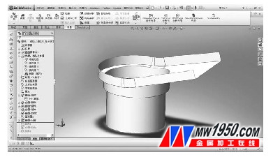
Figure 1 model diagram 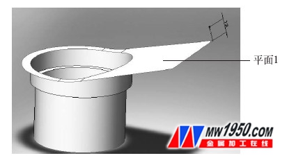
Figure 2 Creating a scan profile 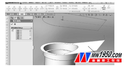
Figure 3 Creating a scan path 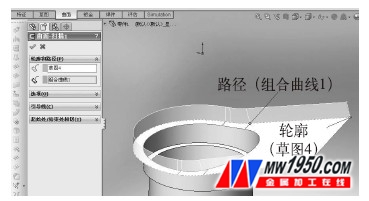
Figure 4 Preview of the scan results 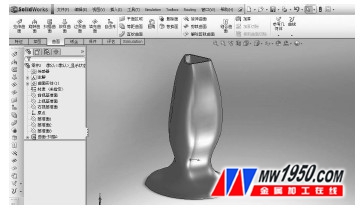
Figure 5 flower arrangement bucket 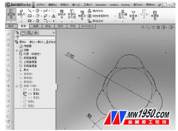
Figure 6 Creating a scan path 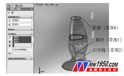
Figure 7 Creating a scan guide