CNC fast wire cutting programming
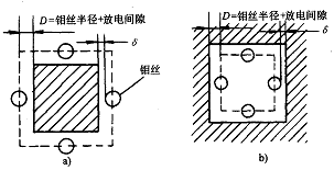
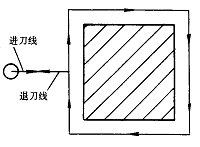
a) machining the punch b) machining the die Figure 1 Schematic diagram of wire radius compensation (2) Selection of process parameters Figure 2 Establishment and cancellation of wire radius compensation (G41) Next page Luminous Ceiling Fan,White Ceiling Fan With Light,Home Decorators Collection Ceiling Fan,Retractable Blade Ceiling Fan JIANGMEN ESCLIGHTING TECHNOLOGY LIMITED , https://www.jmesclightingfan.com
For simple planar 2D contour parts: manual programming is generally used;
For the processing of up and down profiled straight surfaces: simple parts can be programmed manually, and complex parts can be graphically aided and computer-aided.
1. Basic technical problems in CNC fast wire cutting
(1) Setting of workpiece coordinate system and workpiece origin
1) Several workpieces can be installed at different positions on the machine table. Several workpiece coordinate systems need to be created.
2) The machine tool generally provides six workpiece coordinate systems, which are specified by G54 to G59.
3) The workpiece origin should be selected for easy measurement or touch position, and it should be easy to program and calculate. 
1) Process parameters: refers to the processing conditions, including: discharge pulse frequency and pulse width, current size, discharge gap and other parameters, these parameters and workpiece material and its heat treatment state, workpiece thickness, processing accuracy, electrode wire (molybdenum wire) The diameter is related.
2) CNC wire-cutting machine tools generally provide a database of process parameters for the processing program to call.
3) The process parameter database can be modified according to the cutting material and thickness.
(3) Correct selection of threading holes, feed lines and retracting lines
1) The threading hole is a process hole that is processed on the workpiece by other processing methods (such as drilling, electric spark perforation) before the wire cutting process.
2) The threading hole is the starting point of the movement of the molybdenum wire relative to the workpiece, and is also the starting position of the program execution.
3) Position of the threading hole: It should be selected in a position that is easy to find and easy to inspect during processing.
4) The position of the threading hole should be set on the workpiece.
5) The selection of the feed line and the retraction line should also be noted.
(4) Establishment of wire radius compensation
1) Calculation method of radius compensation value: radius compensation value == molybdenum wire radius + discharge gap
Namely: D = wire radius + δ (δ is the discharge gap)
2) The establishment and cancellation of the wire radius compensation is exactly the same as the compensation process in the CNC milling process.
3) The establishment and cancellation of the wire radius compensation must be performed with the G01 linear interpolation command, and must be completed in the cutting process (infeed line) and the cutting process (retraction line), as shown in Figure 2. 