CW6200 crankshaft is the main production crankshaft of our company. As of the end of October 2012, more than 2,000 CW6200 crankshaft forgings have been produced. In recent years, the output of this product has been 200/year, which is far from the demand of 1,500 users. The CW6200 crankshaft has an annual production capacity of over 500. If the manufacturing cost of the product is lowered, it will certainly create huge economic benefits for the enterprise, and the level of forging technology of the enterprise can be improved. Therefore, the optimization of the upsetting process of the CW6200 crankshaft RR method is proposed. The design principle of this process optimization is to reduce the machining allowance of the crankshaft forgings and reduce the use specifications of the crank bar stock, thereby reducing the purchase weight of raw materials and reducing the manufacturing cost.
First, the process optimization program
1. Crankshaft forging crank process optimization program
The CW6200 crankshaft consists of one flange plus six cranks with an angle of 120°. The finished crank plate is very thin, only 60mm, the main journal is f161mm×74mm, and the connecting rod neck is f141mm×87mm. Such a crankshaft structure causes the crank that participates in positioning during crankshaft upsetting to be easily deformed; at the same time, the main journal and the connecting rod neck are thin, the overall rigidity of the crankshaft is poor, and bending deformation is easy; the spindle neck opening and the connecting rod neck opening are small. The mold baffle is thin, easy to deform and has a low life.
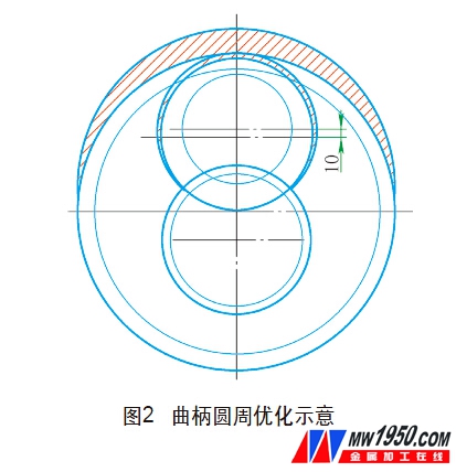
(1) Reduce the crank radius and the outer circumference of the crank to redesign the crank shape and reduce the machining allowance of the outer circumference of the crank. In order to further compress the margin, the design of the radius of the forged piece is reduced, and the long axis of the crank ellipse is reduced, thereby reducing the projected area of ​​the crank circumference. The optimized crank is closer to a perfect circle, and the crank is formed into an upset shape, which is more conducive to full shaping according to the metal minimum resistance flow principle. As shown in Fig. 2, the outer solid line is the outer contour of the crank forging, the double-dotted line is the crank finished dimension line, and the part between the double-dotted line and the thick solid line is designed for machining allowance. The shaded part in the figure is the forged residual block that is removed before and after the optimization of the outer circumference of the crank. It can be seen from the figure that by reducing the design of the crank radius of the crankshaft forging, the radius of the forging piece is reduced by 10 mm, and the machining allowance is used to ensure the size of the connecting rod neck and the main neck of the spindle, so that the outer circumference of the crank is machined. The amount is more uniform to achieve a "net near" forging shape. Using the three-dimensional modeling software to simulate and compare the optimization, the weight of the forged block is 6.67kg, and the CW6200 crankshaft has a total of 12 cranks. The crank weight loss can reach 6.67×12=80(kg).


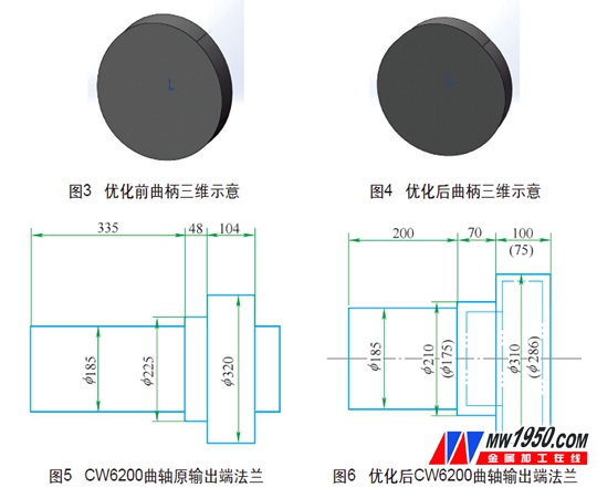
(2) Reducing the crank thickness of the forgings The axial margin of the crank forgings is reduced from the original 10.5mm to 8.5mm. CW6200 crankshaft finished crank thickness is 60mm, original forging design is 81mm, now unilateral minus 2mm, forging crank thickness is designed to 77mm. Combining the above two optimization schemes, using 3D modeling software to simulate and compare the weight loss of a single crank before and after optimization is 77.6-67.3=10.3 (kg), then the CW6200 crankshaft crank weight loss is 10.3×12=123.6 (kg) (see Figure 3, Figure) 4).
2. Flange process optimization program
Reduce the axial margin of the flange by 2mm on one side, reduce the circumferential margin of the flange by 5mm, and subtract 135mm from the output neck, as shown in Figure 4 and Figure 5. Optimized by this process, the weight loss is 31kg (see Figure 6).
Second, reduce the use of crankshaft bar specifications
1.RR method for full fiber crankshaft upsetting process design program
(1) Drawing the crankshaft forgings according to the rough drawing of the lower process, and determining the remaining amount and residual block of each part of the crankshaft according to the characteristics of the RR upsetting process.
(2) Calculate the volume of each part of the crank, and design the single-turn crankshaft test step axis according to the volume-changing principle (considering the fire), and finally determine the step axis according to the test conditions.
(3) Calculate relevant parameters according to the structural dimensions of the crankshaft forging and the structural dimensions of the RR device.
(4) Draw the use diagram and deformation map of the RR crankshaft forging step mold, and the deformation diagram is used to guide the workers' operation.
(5) Mold design. It can be seen from the process design program that the process size of the crankshaft forging is designed according to the rough drawing of the lower process. The roughing process size is based on the crankshaft finished drawing considering the machining machine clamping, heat treatment lifting and heat treatment deformation. The impact of the formation. Crankshaft forgings are designed with consideration of the balance of the allowance, the length of the forging, the deviation of the crank angle, the straightness, the deviation of the radius of the crank, and the process characteristics of the RR method. The length of the crankshaft forging step shaft is determined according to the principle of volume invariance (considering fire consumption), and the length of the light bar is determined according to the length of the step shaft.
2. CW6200 crankshaft light bar ordering material size determination
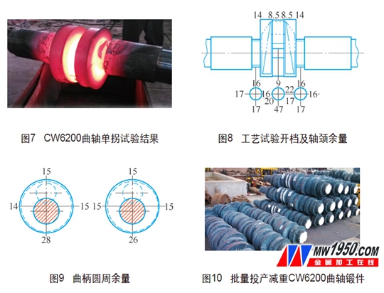
The most fundamental way to reduce the forging of raw materials is to minimize the volume of the ordered bar material while meeting the forging process. Mainly from two aspects: bar diameter, length. The diameter of the bar is determined according to the upsetting method and the diameter of the main journal. Generally, the bar diameter is 20 to 35 mm larger than the diameter of the main journal. The CW6200 crankshaft spindle neck forging is designed to be f185mm, and its bar diameter is 210. It is verified by the single-turn crankshaft test that the bar diameter meets the crank shape, as shown in Figure 7. Considering that the ultrasonic testing of raw materials after entering the factory requires the surface of the machined bar to meet the testing requirements, the order bar diameter is 213mm. According to the principle of volume constant (considering burning loss), the CW6200 crankshaft light bar ordering size is f213mm×4830mm, the original material size is f228mm×4865mm, and the raw material purchasing weight is reduced by 1560-1350=210(kg).

Third, process optimization results
1. Process test results
The test results of the process test are shown in Fig. 8 and Fig. 9. The inspection standard is the finished drawing of the crankshaft. The forging allowance is uniform. Only the balance of the top of the connecting rod neck is small. The radius of the inspection crank is 116mm, and the forging design is 125mm. The radius of the crank can be increased by adjusting the bending die gasket to ensure the balance of the top of the connecting rod neck.
2. Mass production
During the mass production process, the radius of the crank is increased by adjusting the bending die gasket, and the balance of the connecting rod neck is uniform. The special crank heating furnace is used to reduce the heat affected zone of the positioning crank, reduce the crank deformation, control the length of the crankshaft, and improve the heating efficiency, thereby greatly reducing the fuel cost. The double positioning deformation process is adopted, and the positioning between the second positioning die and the positioning surface is considered to be a gap between the thermal expansion and contraction of the positioning crank, and the deformation of the positioning crank when participating in the positioning is reduced. At the same time, the second positioning mode corrects the crankshaft, reducing the crankshaft curvature. This process innovation mold is optimized before the CW6200 mold restructuring, which greatly reduces the cost of the process optimization. The mold modification system abandoned the original large-cavity universal positioning mold design, and the positioning model cavity similar to the outer contour of the crank increased the rigidity of the mold and prolonged the life of the mold.
3. Optimization results
Calculated based on the annual production of 500 CW6200 crankshafts, the CW6200 crankshaft is made of 45 steel. At present, the purchase price of raw materials is 12 yuan/kg. The annual purchase cost of raw materials can save 500×210×12=126 (ten thousand yuan). By using a special crank heating furnace, the heating efficiency is increased, which is 2/3 of the original heating time, and the burning cost of 500 can save 312,000 yuan. The optimization of the process basically realizes the "net near" forming of the forging, the machining cost and the tool cost are reduced, and the reduction of 500 pieces can reduce the cost by 200,000 yuan. The process optimization can achieve a cost savings of more than 1.7 million yuan per year.
Fourth, the conclusion
This process optimization reduces the manufacturing cost of the CW6200 crankshaft and creates benefits for the enterprise. Medium frequency induction heating instead of natural gas heating can reduce energy consumption and improve heating quality, and can further optimize crankshaft forgings to reduce manufacturing costs. The success of this process optimization has accumulated data and experience for the optimization of the crankshaft RR process. However, the special crankshaft upsetting device is bound to become the development direction, and the crankshaft forging can be further optimized to achieve precision forging.
references:
[1] W.Walczyk.TR35Z device molding process design [M]. Polish Metal Forming Institute, 2003.
[2] Feng Daowu. Production of TR Upset Crankshaft [J]. Large Casting and Forging, 1994, (2): 4-10.
[3]Wan Yiyi. Discussion on Forging Method of Large Whole Fiber Crankshaft[J].Large Casting and Forging,2006(3):45-52.
[4] Mechanical Industry Vocational Skills Identification Center Group. Forging Technology [M]. Beijing Mechanical Industry Press, 2000.
About the author: Pan Mingming, Crankshaft Division of CSR Ziyang Locomotive Co., Ltd.
PPGI And PPGL With Different Designs
PPGL Sheet,PPGI Sheet,PPGI Profile Sheet,Galvanized Roofing Sheet
SHAOXING YOTO IMPORT&EXPORT CO., LTD , https://www.sxyoto.com


