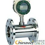
Considerations for the operation of the turbine flowmeter
1 use of each way
1.1 After installation, ensure that all chips and debris have been removed and the system has been purged, pressure tested, airflow in and boosted to flow.
Meter inlet valve.
1.2 Open the upstream flow ball valve of the turbine flow meter
1.3 Slowly open the bypass small bypass valve upstream of the turbine flowmeter, and slowly fill the gas until the turbine is downstream of the electric flow forced ball valve.
Note: High-speed pressurization with severe pressure or excessive pressure can damage the turbine flowmeter. In order to protect the gas turbine flow meter, it is added to the turbine flow meter.
The pressure rise cannot exceed 35 kPa/s. If the pressure change cannot be measured at the site, the monitoring turbine flow rate cannot be exceeded.
1.4 Close the bypass ball valve and shutoff valve.
1.5 Turn the handwheel to open the inlet force seal valve.
1.6 Slowly open the electric forced sealing ball valve downstream of the turbine flow meter (for at least 1 minute), preferably using manual opening on the electric actuator
Be careful, be careful not to overrun the turbine flow meter.
1.7 According to the steps 1.2-1.6, the whole system is pressurized and the natural gas is measured.
2 Online comparison gas turbine flowmeter (work path and main road comparison)
2.1 Make sure that the inlet and outlet valves of the main road are closed.
2.2 Fill the main circuit according to steps 1.2, 1.3, and 1.4 in “1 Use of Each Pathâ€.
2.3 Close the working circuit outlet electric forced sealing ball valve, slowly open the forced sealing ball valve of the comparison pipe, and slowly open the main circuit outlet electric forced sealing ball valve.
It is best to do three things at the same time.
2.4 The gas passes through the working and main paths in sequence. The two turbine meters can be compared to each other to check for large deviations.
2.5 When the comparison is over, close the two forced sealing ball valves on the comparison line and on the main line and open the outlet ball valve of the working line.
It is best to do these three tasks at the same time.
2.6 At this time, the work road is back to work.
3 Online calibration of gas turbine flowmeter with mobile calibration vehicle
3.1 Ensure that the electric forced seal ball valve between the two calibration ports is closed.
3.2 Open the small ball valve on the blind flange of the calibration port to ensure that there is no pressure inside the flange blank plate. Then remove the flange blind plate.
3.3 Connect the mobile calibration vehicle to the calibration port.
3.4 Press the steps 1.2, 1.3, and 1.4 in “1 Use of each channel†to pressurize the main circuit.
3.5 Close the working circuit outlet electric forced sealing ball valve, slowly open the forced sealing ball valve of the comparison pipeline, and slowly open the two calibration forced sealing ball valves on the main road. It is best to do these four tasks at the same time.
3.6 At this point, the gas flows through the two gas turbine flow meters and the mobile calibration vehicle in the sled seat in sequence.
3.7 After completing the online calibration, close the two Orbit ball valves of the calibration port, slowly open the forced sealing ball valve of the comparison pipe, and slowly open the working circuit outlet electric forced sealing ball valve. It is best to do these four tasks at the same time.
3.8 Replace the flange blank plate and do not forget to close the small ball valve on the flange blind plate.
3.9 At this time, the work road is back to work.
Turbine Flowmeter Order Hotline
This article is from http:// 