HyperMesh in the calculation of the strength of the transfer case (Figure)
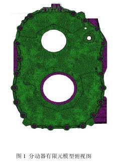
1 Analysis purpose The transfer case of a car is made of a special material. The stress distribution of the transfer case is now analyzed by finite element to verify whether the stress exceeds the yield limit of the material. 2 Establishment and calculation analysis of finite element model Figure 1 is a top view of the transfer case model. The transfer case is composed of two front and rear housings, the front case being the front case of the transfer case, and the rear case being the rear case of the transfer case. In the upper part of the figure, the front part is the front case input shaft hole, the rear part is the rear case input shaft hole; the lower part of the lower hole is the front bridge output shaft hole, and the rear part is the middle rear axle output shaft hole. . The support at both ends of the transfer case is caught by the other components on the surface of the support. In the model, six degrees of freedom are imposed on all nodes on the support surface (including the bolt holes on the support surface). Figure 2 and Figure 3 show the finite element model diagrams of the front and rear casings after applying the boundary conditions. Next page Ultraviolet Lamp,Pll Uvc Tube,Pll Uvc Light,Pll Uvc Bulb Changxing leboom lighting product CO.Ltd. , https://www.leboomuv.com
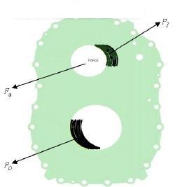
Finite element analysis of the transfer case is performed using HyperMesh. In the calculation, the casing itself consists of tetrahedral solid elements with a cell size of 3 mm. The front and rear housings of the transfer case are connected by a rigid connection unit. The total number of nodes in this model is 507,261, the total number of units is 2,184,372, and the total number of rigid units is 71. It is now known that the orifice of the transfer case is subjected to a tangential force Ft perpendicular to the radius of the hole, a radial force Fr parallel to the radius of the hole and an axial force Fa perpendicular to the face of the hole. In the calculation, it is assumed that the contact surface of the combined force of the radial force and the tangential force is a 90 degree arc and is loaded into the input shaft hole and the output shaft hole of the model in the form of uniform loads PI and PO, and the axial force Fa is loaded into the model in a concentrated manner. 
Figure 2 Front shell finite element model after applying boundary conditions