Spherical surface grinder for micrometers and internal gauges
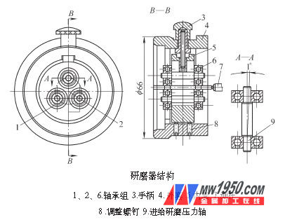
The identification and repair of measuring tools is two important aspects of the measurement work, and is an important means to ensure the uniformity of the quantity. In order to adopt a more complete measurement and repair method in the repair process, based on the field work experience, based on the collection of domestic and foreign gage repair data, the design of the measuring rod for the most used micrometer and inner gauge in the production is designed. A grinder was made to solve the problem of grinding repair. 1. Structure of the grinder The grinder is mainly composed of a handle, a jacket, an inner sleeve, a rolling bearing and an adjusting screw, and the structure is as shown in the drawing. Working principle: The grinder is equipped with three sets of rolling bearings, each consisting of two bearings, two sets of bearing sets 1 and 2 are fixed, and a set of bearing sets 6 can be moved along the square groove on the inner sleeve for clamping test Rod. The inner sleeve is fixed in the outer casing with 6 adjusting screws. When grinding, the clamp is placed on the grinding plate, the measuring rod is inserted between the three sets of bearings, and the rotating handle holds the measuring rod. The degree of clamping is limited by the fact that the hand can gently rotate the spindle without swinging. Then push the clamps back and forth, left and right, and rotate the spindle clockwise to rotate. In the design, the axis of the bearing set 6 and the two sets of bearings are inclined to 1°. When the spindle needs to be rotated clockwise, the measuring rod moves downward along the spiral line, and contacts the grinding plate to generate pressure, and the measuring rod is pushed up again due to the gravity of the grinder itself. Keep the measuring surface of the measuring rod in the same plane as the grinding base of the grinder. Therefore, when the measuring rod is continuously rotated during grinding, the measuring surface is subjected to a large grinding pressure. The grinding base mainly serves as an auxiliary and the grinding amount is small. This not only shows that the measuring rod is rotationally ground in the fixture, and the measuring rod axis is perpendicular to the grinding base surface, so that the measurement is perpendicular to the axis of the measuring rod. The requirements for the preparation of the grinder should be noted: (1) Model 1000805 deep groove ball bearings used in this grinder bearing. (2) Feed the center line of the grinding pressure shaft, and the angle between the fitting and the inner sleeve axis is about 1°. (3) The feed grinding pressure shaft should not be loosened with the square groove, and the matching clearance should not exceed 0.02mm. (4) The inner sleeves of the bearing sets 1 and 2 are tightly fitted, the parallelism of the two axes is not more than 0.01 mm, and the perpendicularity between the two axes and the lower end surface of the inner sleeve is not more than 0.01 mm. (5) The adjusting screw should be made of fine thread to facilitate adjustment. After adjustment, it must be fastened and reliable, and should not be loose. 2. Grinding method adjustment (1) Flat crystal adjustment method Insert a new micrometer movable measuring rod whose measuring plane is flat and high and the measuring surface is perpendicular to the axis of the measuring rod as a standard measuring rod, properly clamp with the handle, and then the diameter is slightly larger than The flat crystal of the diameter of the grinder is placed on the base surface, and the measuring rod is rotated to bring the measuring surface into contact with the flat crystal, and the contact is observed by the interference belt. If the measuring surface is not perpendicular to the axis of the spindle, the six screws on the outer casing of the grinder can be repeatedly adjusted until the measuring surface is in full contact with the flat crystal. The number and shape of the interference fringe are the same as when the individual is detected. After adjustment, the 6 screws need to be tightened. The grinder can then be used for a long time. (2) Test adjustment method Insert a standard rod into the grinder. Fasten the grinding plate twice and push it twice (note that the measuring rod is not rotated) and then determine the tilting direction of the axis of the measuring rod according to the grinding marks on the measuring surface, and adjust with screws. After adjustment, the rod can be rotated by rotating the rod on the plate. 3. Field verification For the grinding machine after manufacturing, a total of 460 micrometers and 306 inner gauges are milled. After the above-mentioned measuring tools are identified and repaired, the metering needs can be fully achieved. The average time to grind a cemented carbide rod was 12.5 min. It is 3 to 5 times higher than the original manual operation. The flatness can reach an interference zone (planar interferometry). The surface roughness and parallelism of the measuring surface of the measuring rod also meet the requirements. 4. Conclusion Designed and manufactured micrometer and internal gauge rod measuring surface grinder, simple structure and convenient operation. The use on site can fully meet the requirements of the site. It provides a reference for the design and manufacture of similar grinders in the future. Ningbo Royalux Lighting Co., Ltd. , https://www.royaluxlite.com